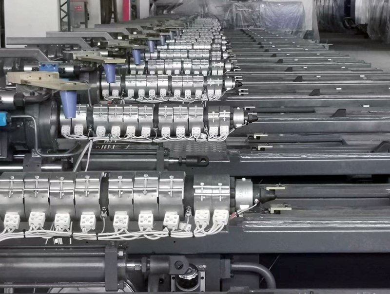
Connecting a limit switch to the core pulling function of a Haichen injection molding machine can enhance safety and prevent interference with the mold’s opening and closing movements.
Here are four steps to guide you through the process:
Step 1: Locate the Input and Output Interface on the Computer/PLC
To begin, navigate to the input and output page on the computer or programmable logic controller (PLC).
Follow this path:
Monitor Page > F10-Next > Group Selection > F4 I/O
1.Monitor page
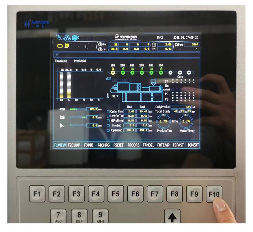
2.Next page F10
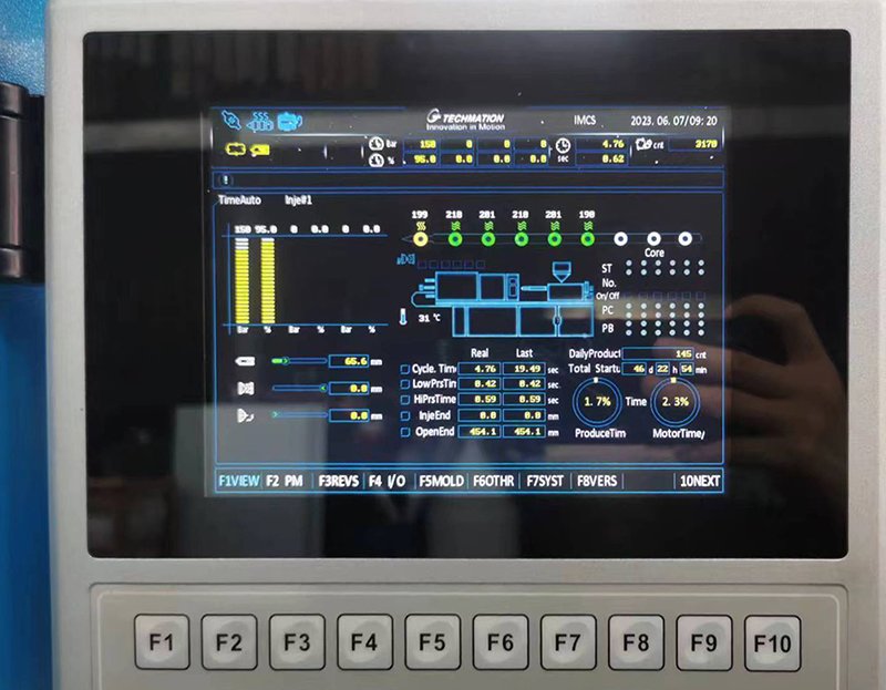
3.I/O page – F4
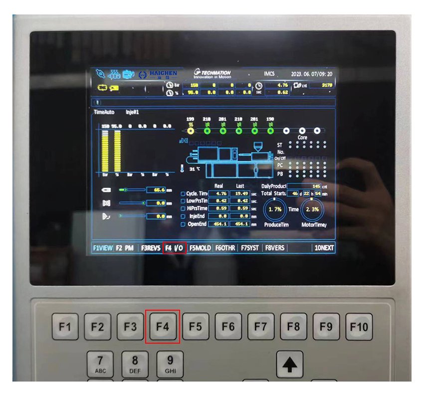
Step 2: Identify the Input and Output Points for Core Pulling
Injection molding machines typically feature multiple sets of core pulling, such as A, B, C, and D. Depending on your machine’s configuration, find the input and output points for each group of core pullers.
The points are usually numbered consistently with the connecting wires.
For instance:
- Core Pulling B: Input point 03, Output point 04
- Core Pulling A: Input point08, Output point 10
- Core Pulling C: Input points 25, 26
- Core Pulling D: Input points 27, 28
Please note that this numbering pattern extends to other core puller groups.
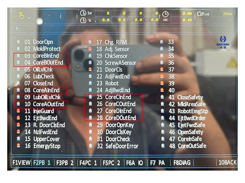
Step 3: Locate the Core Pulling Junction Box on the Machine
Once you have identified the corresponding connection points, locate the junction box of the core pulling valve board on the machine.
These junction boxes are typically situated on the moving template or the rear side of the injection molding machine, near the mold oil cylinder.
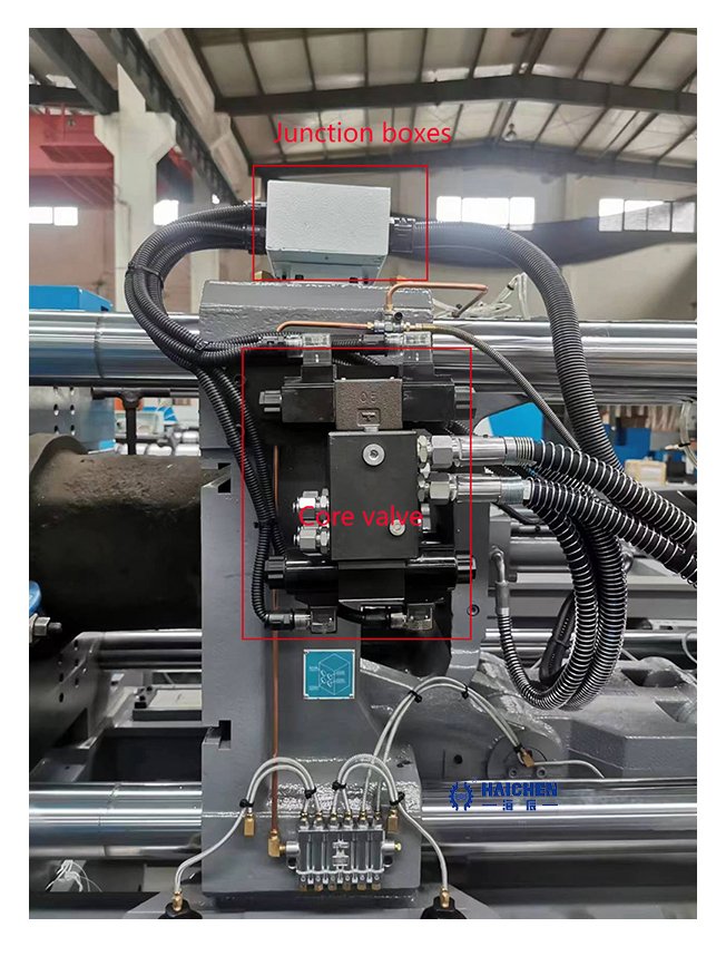
Look for a wiring diagram adjacent to the junction box to assist you,which near by the core valve.
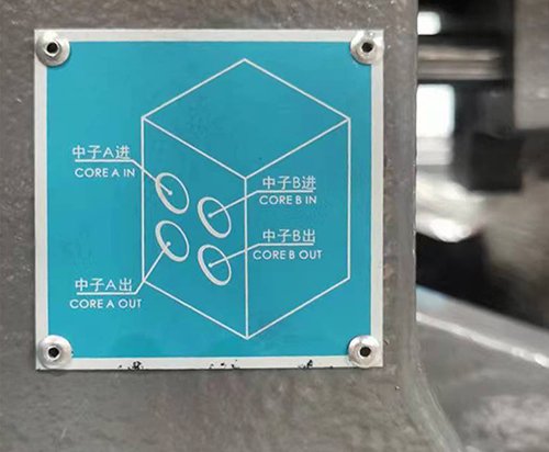
Step 4: Connect the Wires to the Respective Points
Open the junction box and locate the terminal block.
Inside the terminal block, you will find the following wiring ports
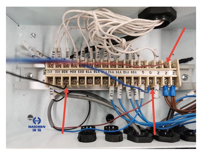
- Z: 24V power connector
- G: Com (common)
- X, Y: Wiring ports with different numbers
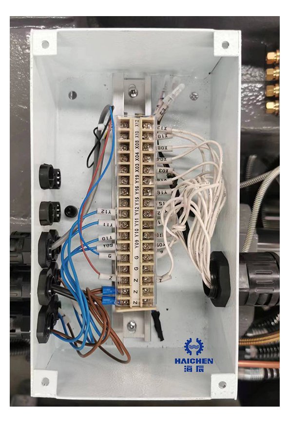
Example for safety switch:
The safety swith with one power connect wire.
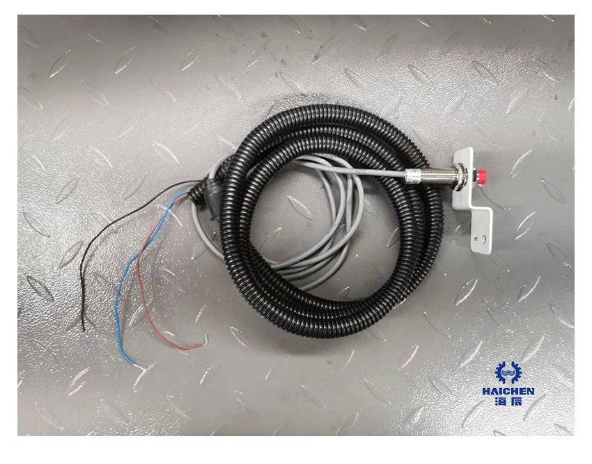
If you are connecting a safety switch to Core Pulling A input (input point 08, output point 10), do the following:
- Connect the power wire of the safety switch to the “Z” port. Ensure that the safety switch operates at 24V before making the connection.
- Connect one wire from the safety switch to the “G” port.
- Connect another wire from the safety switch to the “X08” port.
Example for limited switch:
The limited switch just have two wires.
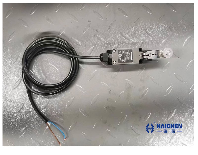
- Connect one wire from the safety switch to the “G” port.
- Connect another wire from the safety switch to the “X08” port.
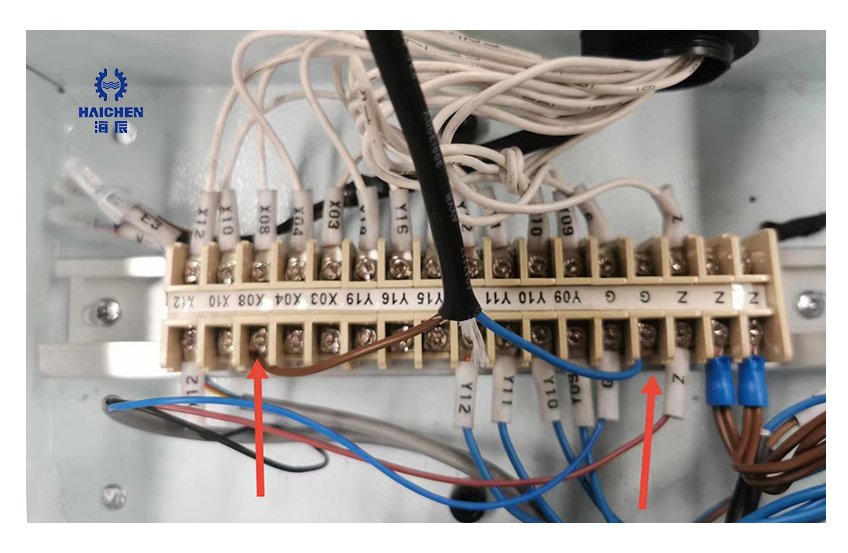
Repeat these steps for other safety switches/limited switch and their corresponding core pulling groups.
By following these four steps, you can successfully connect the limit switch to the core pulling mechanism of your Haichen injection molding machine, ensuring safety and smooth operation during the molding process.